A 5-axis CNC reports how every cut is going while it happens, but most plants only judge the cut by the part that comes off the machine. By then it’s too late to change anything. A good part gets no questions, and a bad one goes in the scrap bin while the team guesses why.
The machine knew sooner. The spindle and servo motors report how hard they’re working. Temperatures climb before bearings fail. Operators key in corrections every time the process drifts. All of that is already sitting in the control, and most of it goes unread.
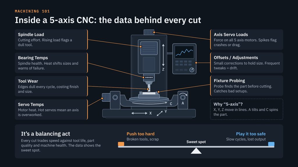
Below are the seven signals worth watching on a 5-axis machine and what each one tells you. Running a CNC well is a balancing act, and these signals tell you how to strike the balance.
Seven 5-axis CNC signals worth watching
Each of these signals comes from a different part of the machine and answers a different question about the cut.
Spindle Load
Spindle load is how much of the spindle motor’s power the cut is using. It’s the most direct measure of how hard the cutter is working. If load climbs over a run on the same job, the tool is usually dulling. If it stays very low, the machine may be cutting air or running more cautiously than it needs to.
Axis Servo Loads
Every axis has its own servo motor, and each one reports the force it takes to move. A sudden spike points to a collision, an unexpectedly heavy cut or packed chips. A slow climb over weeks points to drag: poor lubrication, damaged way covers or a wearing ballscrew.
Servo Temperatures
Servo temperatures show how hard those motors are working over time. A servo that runs hot is near its limit, either because the cycle is too aggressive or because something mechanical is fighting it. Heat also feeds thermal growth in the machine’s structure, which costs accuracy.
Spindle Bearing Temperatures
The spindle bearings carry the cutting load at very high speed, and heat is their warning light. As the spindle warms, it grows, and that growth shifts the tool tip and the size of the part. A sudden rise is often the first sign of a bearing problem, well before an expensive spindle rebuild.
Tool Wear
Every part dulls the cutting edge a little. Wear shows up as rising spindle load, a worse surface finish and features drifting out of size. Change tools too late and you get scrap or breakage. Change them too early and you’re throwing away tool life which can be costly (and some tools can be hard to procure or have long lead times due to rare earth metal content in them).
Offsets and Adjustments
Offsets are the small corrections operators enter to keep parts on size, such as a tool wear offset or a shifted work offset. A few are normal. A steady stream of them means the process is drifting and someone is chasing it by hand, often without a record of why.
Fixture Probing
Before cutting starts, a touch probe in the spindle can find where the part and fixture actually sit. The machine then cuts from where the part really is, not where it’s supposed to be. Probing catches a bad setup, a chip under the part or a shifted fixture before the problem turns into scrap.
Running a CNC is a balancing act
Every cut trades speed against tool life, part quality and machine health, and the sweet spot sits between two ways of getting it wrong. Push feeds and speeds harder and cycle times drop, until tools break, parts scrap and the machine wears out early. Play it safe and the machine stays healthy, but the parts take longer and capacity goes unused.
| Push too hard | Sweet spot | Play it too safe | |
| Cycle Time | Short, until something fails | As short as the process can hold | Longer than it needs to be |
| Tool Life | Broken or burned-up tools | Tools used to their full life | Tools retired early |
| Part Quality | Chatter, drift, scrap | Parts on size, run after run | Good, but at a higher cost per part |
| Machine Health | Hot servos, worn spindle bearings, more frequent maintenance | Loads and temperatures inside normal bands | Healthy, but underused |
The hard part is that the line isn’t fixed. It moves with the material, the tool, the fixture, the machine’s temperature and how worn everything is already. A feed rate that was right on Monday morning may be too aggressive by Friday afternoon. That’s why one-time tuning doesn’t hold, and why the seven signals above matter.
Read the signals together
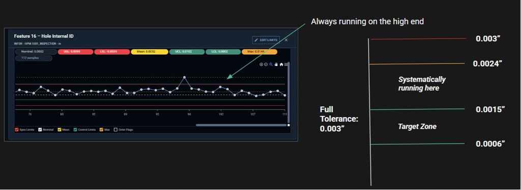
No single number tells you where the line is, but patterns across signals usually do. A spindle load spike on its own could mean many things. Together with an axis servo spike at the same moment, it almost always means the machine hit something.
| What you see | What it usually means | Where to look |
| Spindle load creeping up over a run, sizes starting to drift | The tool is wearing | Tool life limits and change intervals |
| Sudden spike on spindle load and one axis servo at once | Collision, packed chips or wrong stock | Stop and inspect before the next cycle |
| Spindle bearing temperature rising while operators adjust Z offsets | Thermal growth in the spindle | Warm-up routine, thermal compensation |
| One axis’s servo load and temperature climbing slowly over weeks | Mechanical drag on that axis | Lubrication, way covers, ballscrew |
| Low spindle load and a long cycle time | Running more cautiously than needed | Room to raise feeds and speeds |
| Probing finds parts out of position, work offsets change often | Setup or fixturing problem | Fixture condition, clamping, chips on locators |
| Many manual wear-offset edits per shift | Process drift being chased by hand | The root cause behind the drift |
Most rows combine two or more signals, and that’s the point. A good machinist does this in their head while standing at the machine. The data lets you do it on every machine, every shift, including the ones nobody is watching.
From watching gauges to closing the loop
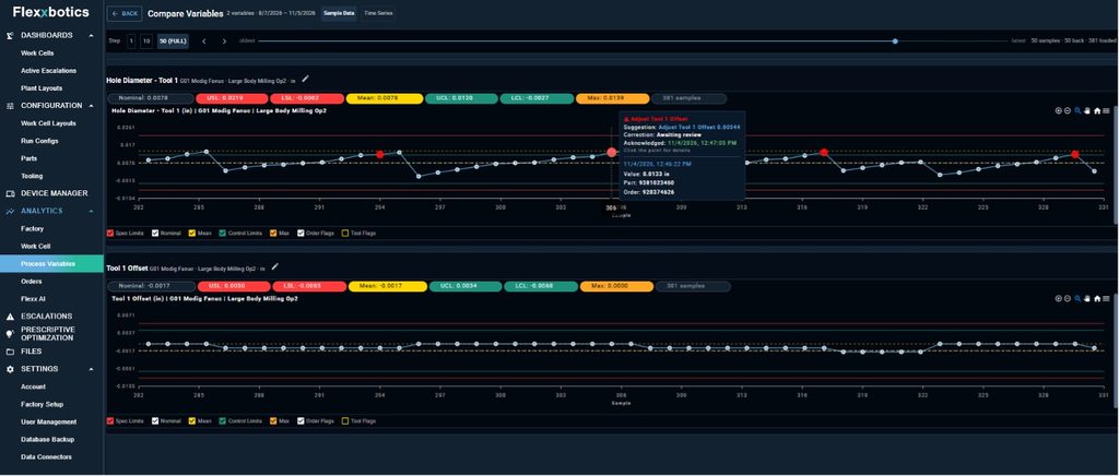
Machine data pays off when it drives decisions automatically, not when it sits on a screen. Today most of these signals live on the machine’s controller, visible only to whoever happens to be standing in front of it. They’re seen in the moment and gone a shift later, never compared across machines or tied to the parts that came out.
Collecting the signals is the first step. Reading them together in machine cycle analysis is the second. The third is closing the loop: using the data to adjust feeds, schedule tool changes, flag a setup before the first cut and keep each machine in its sweet spot without someone watching gauges.
That’s just some of the work that the Flexxbotics Platform does; connecting machines like these and turning their data into process characterization for closed-loop production and autonomous process control.
Your machines are already reporting all these signals. The opportunity is to start acting proactively on them.